All posts by Doug

Century_Redds_Park-5491

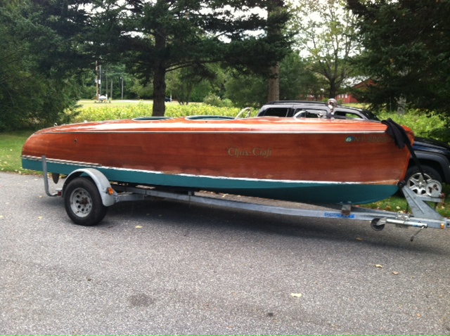
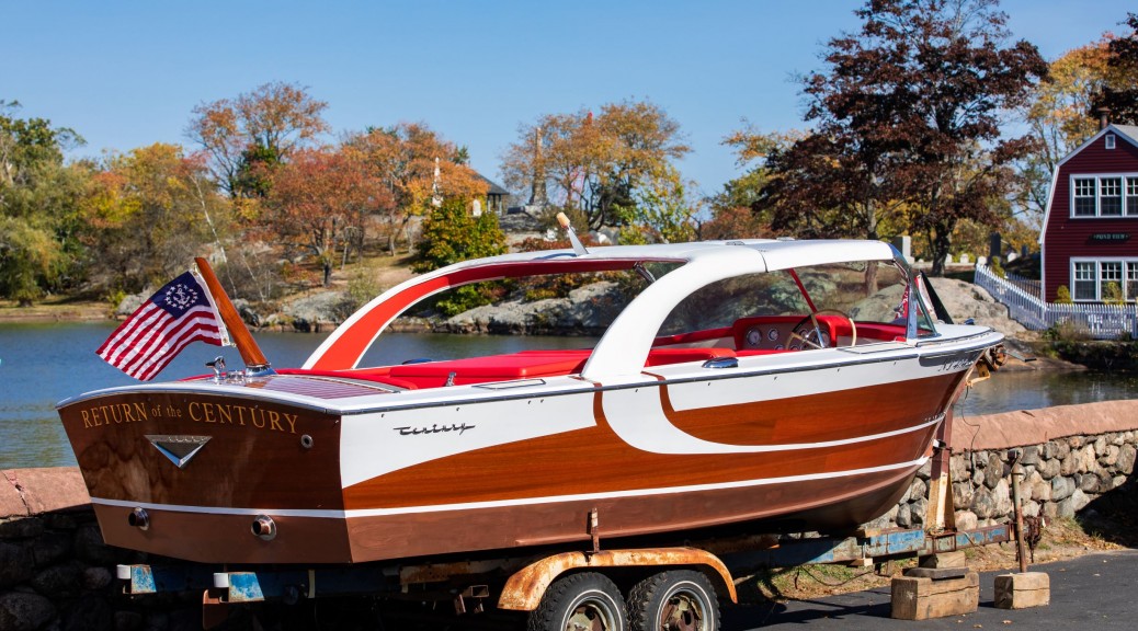
1961 Century Coronado “Return of the Century”

This project started with a customer who came to Redd’s Pond looking for a Century Coronado like one he remembered from his teens. We scoured the internet for a months looking for candidates and ultimately found this one about 45 mins from our shop. we set up a visit, and found that it was a perfect restoration candidate.

DSC06842 sm

What we found is a  1961 Century Coronado with a restoration initiated 20 years ago, but never finished. While the previous owners did a great job tracking down almost every bit of chrome hardware and engine part almost all the woodworking remained.  Some structural work had been done in the stem and topsides frames, but otherwise most of the boat needed replacement.

I usually start a project like this documenting where everything I take off goes to guide reassembly, but in this case I had to start by trying to re-assemble the interior first to get an idea of what the interior looked like and to see if anything was missing.

engine box looking forward. The forwad bench and windsheild were only dropped in for a second
engine box looking forward. The forward bench and windshield were only dropped in for a second
looking aft from the middle bench. - Some upholstry remained, but would all be replaced.
looking aft from the middle bench. – Some upholstery remained, but would all be replaced.

From there I removed all of the interior I could and built a series of internal molds to retain the hull’s shape during the restoration and support it while upside down. We then rolled the hull over to remove the bottom planking.

Interior molds and legs built to hold boat in shape while bottom is removed and replaced. lifting and flipping jig assembled around it so I could flip it in place.

The old bottom planks were removed and saved for templates as well as the keel while half the bottom frames (every other one so the hull stayed together and kept it’s shape).

The old battens had some wiggles which I wanted to straighten out, so the original locations were marked, but not cut untill I could establish fair lines.
half the new frames dry fit before priming with the new keel in place to keep them centered.

Once the first half of the frames were replaced and fastened to the chines and topsides the other half of the frames were removed and replaced. The new keel was bolted down, then new plank battens fabricated and set into notches cut to match re-faired plank lines .

The Transom bow had been replace in the previous restoration work, but we re-established symmetry and adjusted the batten placement.
The Transom bow had been replaced in the previous restoration work, but we re-established symmetry and adjusted the batten placement.
All parts snaded and primed before assembly to keep the bilge cleaner, and give all structural parts a better fight against rot in the future.
All parts were sanded and primed before assembly to keep the bilge cleaner, and give all structural parts better resistance to rot in the future.
All new frames installed and back primed with original century colored bilge paint. Batten faired and dry fit before back priming and bedding.

This was a great opportunity to double check fairness of the plank lines as well as the bottom of the hull. we made sure to double check symmetry, and a little fairing at the transom to help the hull get up on a plane as well as general smoothness.


Next came bottom planking. Since we had almost all the original planks we had general templates to rough out the planking stock. We were able to get some 1 1/2″ thick mahogany stock that allowed us to  make pairs of planks from a single board sawn down the middle, which not only saved time, but led to a lot less wasted material going into the trash.

Our bandsaw took a little tuning to be up to this task, but once it was dialed in, we were able to easily re-saw the 8-12" wide stock allowing us to sometimes place multiple plank pairs on a single board. Rollers leading to and from the saw allowed this to be a one person job.
Our bandsaw took a little tuning to be up to this task, but once it was dialed in, I was able to easily re-saw the 8-12″ wide stock allowing us to place multiple plank pairs on a single board. Rollers leading to and from the saw allowed this to be a one person job.

Once the bottom planks were made up and fit tight, we shaved a little of each edge, sanded, sealed the insides with Smith’s CPES and Century red bilge paint and then set all the planks in 5200 marine adhesive before fastening down. The small gaps and flexible glue allow the bottom to swell when soaked without applying too much pressure to the chines and pushing them out, while also having a rubber-gasket seal between every plank even when it has been out of the water and dried out for months. The bottom was then faired and sanded smooth with all screws set low enough to have a putty or wooden bung cover depdending on if it would be painted or varnished.


midway through bottom planking. plastic tubes were used to steam planks prior to being bent into place.
Midway through bottom planking. plastic tubes were used as steam boxes to steam planks prior to being bent into place.
Bottom planking installed prior to removal for back priming. I used as few fasteners as I could so the final instalation were as clean as possible, especially where they would be varnished.
Bottom planking installed prior to removal for back priming. I used as few fasteners as I could so the final installation was as clean as possible, especially at the bow where the ends of the planks would be varnished.

The topsides planks that were still on the boat were then removed as well for templating and the topsides and transom frames were inspected and repaired or replaced as necessary. The battens and the topsides planks were replaced again with re-sawn 6/4 stock being sure to prioritize  quarter-sawn stock to ensure stability as well as aesthetics.

topsides planks steamed in for a few days ahead while I fit the other planks and fasten them helps cut down on lost time. A day or two clamped leads to less stress when fitting and fastening.
Topsides planks steam bent in place and left clamped for a few days ahead while I fit the other planks and fasten them. This helps cut down on lost time. A day or two clamped into the curve leads to less stress when fitting and fastening.
Topsides aft planks left long to be trimmed when applying the transom planks to the stern.
The transom planks were last as Century applied the transom to the cover the ends of the side planks. The upper transom frame was replace as we found that it had been previously replaced and didn't have the correct radius adn was starting to rot on the ends.
The transom planks were last as Century applied the transom to the cover the ends of the side planks. The upper transom frame was replaced as we found that it had been previously replaced with incorrect radius and was starting to rot on the ends.
The transom planking complete.
Once topsides planking was done, rough fairing started and any screws too close to the surface were re-set.
Once fairing was getting close to done bungs are set in and trimmed for final fairing.
Final fairing before bottom paint. the bottom screws just receive a putty bung as they won't be visable.
Final fairing before bottom paint. the bottom planks’  screws receive a putty bung as they won’t be visible.

With the planking all completed, below the waterline was again faired, and the waterline marked off. Then a 2 day soak under a thin plastic sheet helped raise the kiln dried wood to a suitable moisture content before being sealed with CPES and covered in copper bronze bottom paint. The boat was then flipped before final sanding of the topsides to re-fit the deck before staining and varnish.

Water under the plastic helps soak the kild dried mahogany a bit to a better moisture content before the outter surface gets it's sealer coats.
Water under the plastic helps soak the kild dried mahogany to a better moisture content before the outer surface is sealed.
Before sealing I aligned the shaft strut and bored through the keel so the bore could be sealed and painted with the rest of the bottom.
Before sealing I aligned the shaft strut and bored through the keel so the bore could be sealed and painted with the rest of the bottom. The temporary block glued to the keel helps guide the start of the cut and prevent blow-out on the edge of the hole. There is a corresponding block on the inside of the hull for the same reason.
I didn't quite get the camera lined up, but you can just make out the cross hairs I was aiming for through the bore.
I didn’t quite get the camera lined up, but you can just make out the cross hairs I was aiming for through the bore.


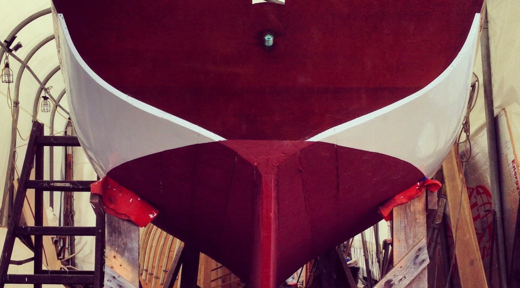
The waterline was scribed on the boat based on the original planking and the bottom painted with InterProtect  and copper bronze bottom paint before setting up the flipping jig and getting her back upright.

While I reused as much of the deck as I could, I ended up replacing the aft deck and a lot of the foredeck due to rot.  With these parts fit, fastened and bunged, I finish sanded all bare wood, stained and varnished 12 coats. While a lot of the topsides and deck would end up painted white with the jet design it was much faster to varnish the whole boat than to try to work around all the curves and edges of the jet and keep them crisp.

Once flipped the old deck was laid out to make sure everything still fit before moving on to make it new.
Once flipped, the old deck was laid out to make sure everything still fit before moving on to make it new.
New aft deck and covering board fit and bored for some hardware. Most of this deck was able to come from a single board and has great color consistency.
New aft deck and covering board being  fit and bored for some hardware.
Here the deck is final sanded with seams routed in for putty and bungs faired down. The color difference between the side deck and new wood will be lessened by stain, but ultimatly hidden by white paint.
Here, the deck is final sanded with seams routed in for putty and bungs faired down. The color difference between the side deck and new wood will be lessened by stain, but ultimately hidden by white paint.
Our shop dog Jasper helping identify any rough spots left after fairing before stain was applied.
Stain starts to even up the color, but blends the new wood together nicely.
bow planks after stain.
Bow planks after stain.
The gloss builds quickly after a couple coats of primer epoxy and a couple coats of varnish.
Bow getting glossy
Bow getting glossy
But after about 10 coats I start checking my reflection.
After about 10 coats I start checking my reflection.

IMG_9257

Once the varnish was built up I worked with a local sign painter to re-develop the shapes for the white paint as well as have the name of the boat lettered in gold leaf on the transom. She pinstriped the outlines on the hull so I could come back and brush more liberally in order to get a really flat coat. 5 coats of varnish were applied on top of the transom lettering to protect it for seasons to come.

with the Jet and other white outlined I painted through with glossy white.
With the Jet and other white outlined I painted through with glossy white.
looks much crisper with the tape off! None of the original paint outline was left on the planks, so she had to work from a bunch of pictures off the internet and shape as best she could.
Looks much crisper with the tape off! None of the original paint outline was left on the planks, so she had to work from a bunch of pictures off the internet and shape as well as she could.
The name is gold leaf with boarder and shadow.

With the hull complete, attention was turned to the interior. The engine box had deteriorated as well as the fore-deck so they were replaced, some of the controls and hardware had been acquired by the previous owner so they were cleaned, reassembled and chromed. Other missing or broken parts were remade and chromed as well. All the benches and side paneling were in good shape and were just cleaned up for being re-covered with vinyl.

We had the original engine box, so this one was fabricated to match.
The original engine box was used to template the new one with marine plywood and fresh oak corners.
The original foredeck was replaced with new marine plywood and mahogany off cuts from the planking
The original foredeck was replaced with new marine plywood and mahogany off cuts from the planking.


The original dash and cowl around the gauges are fiberglass molded peices that are later wraped in matting and vinyl.
The original dash and cowl around the gauges are fiberglass molded pieces that are later wrapped in matting and vinyl.
Deck hardware and cutwater fastened on.


The boat was then fully reassembled with all hardware and hard top and sent off to an upholstry shop to install the vinyl kit made from the original factory templates.

The vinyl was re-made to original templates in a kit and installed by local upholstery group.

Forward dash with vinyl installed.
Engine box with vinyl installed.
Boat on jacks to get on moving truck to come back to shop for systems installation.
Boat on jacks to get on moving truck to come back to Redd’s Pond shop for systems installation.


The engine was re-assembled, painted and test run by a local mechanic and finally the boat was re-wired with modern safety components such a main battery switch, a bilge blower and updated wiring.

327 Grey Marine Fireball V8 after re-build
Benches cleared out so the electrician could re-wire the boat and plumb fuel/exhaust.


Once the engine was test run and tuned and all wiring installed and tested, I invited a local friend to come take photos of the boat while we waited for a transportation company to truck it out to her new home in western New York.

This slideshow requires JavaScript.

The boat is currently being stored for the winter awaiting summer commissioning. Check back for photos and videos of it running in the lake.

The first coats of primer are applied while the boat is upside down and more accessible.

Herreshoff S-class Arete #2

Dry fit mast staves to test joints and geometry. the 5 staves are glued up as one, then internal blocking fit adn finally the last three staves glued on top.
Fairing out the curve of the mast in preparation for glue up.
The upper deadwood is dry fit to the oak backer roughed opt to width to be final faired on the boat
without a 30' steam box the keel was steamed in a bag with steam generators piped in from both ends.
without a 30′ steam box the keel was steamed in a bag with steam generators piped in from both ends.
without a 30' steam box the keel was steamed in a bag with steam generators piped in from both ends.
without a 30′ steam box the keel was steamed in a bag with steam generators piped in from both ends.
without a 30' steam box the keel was steamed in a bag with steam generators piped in from both ends.
without a 30′ steam box the keel was steamed in a bag with steam generators piped in from both ends.
without a 30' steam box the keel was steamed in a bag with steam generators piped in from both ends.
without a 30′ steam box the keel was steamed in a bag with steam generators piped in from both ends.
Once clamed to position the bag is removed to allow the keel to cool and maintain the shape.

keel clamped down

All the clamps in the shop were used to get the mast glued up

mast glue up

Here the backbone assembly has been bolted together and the garboard installed. the battens define plank lines as I go down the hull. Since the boat is being rebuilt over molds I was able to template one side for planks on both sides. Heere the transom frame is also installed but left tall to be finished when installing the deck.
Here the forward section of keel and stem are bolted together and the garboard installed.
planking continues from the keel down until the planks run full length to the transom. At that point the sheer plank is installed and planking is completed from the bottom up as well to improve efficiency.
At this point the old planks are removed so we can continue to check fair of the frames that dont have molds.
the shape of the molded sheer profile is roughed out with a radial arm saw on an angle and a quarter round router bit on the top.
Sheer plank installed and starting to plank in both directions. Planks are let to run long past the transom and will be trimmed to fit the transom plank later. All surfaced between planks and frames are back primed to help preserve the wood and lower planks are bedded to keep water out from between the surfaces.

Planking continues

each plank is roughed to final thickness on the corners so when fairing we don't remove too little or too much material. The internal surfaces are shaped sanded and painted, but the outer are left mostly rough to be faired once the whole shape is developed.
each plank is roughed to final thickness on the corners so when fairing we don’t remove too little or too much material. The internal surfaces are shaped sanded and painted, but the outer are left mostly rough to be faired once the whole shape is developed.

DSC05768

the final plank is called the shutter plank. the mast can be seen glued up and hanging on the side of the tent.
the last plank is hard to clamp, so I used small boards tied off to the structure of the building jig and wedges to push the plank in as the fit was finalized and the plank fastened in. Any imperfections in the planking wer fixed at this point brefore fairing.
I made a transom template of the inner and outter faces fo the transom to trim the aft ends of the planking so it fit well before bringing in the solid 3/4" white oak transom planks.
I made a transom template of the inner and outter faces fo the transom to trim the aft ends of the planking so it fit well before bringing in the solid 3/4″ white oak transom planks.
Here the fit is getting close, some gap can still be seen near the sheer to the left.
Fairing the hull with a stiff long sanding board. Initially the hull is rough planed, then sanded smooth.
Once sanded fair the screws are all sunk to a final depth and bunged over.

DSC06254 bow bungs DSC06275

Once the bungs are trimmed off and sanded smooth I scribed in a waterline and drove cotton caulking into the seams.


Here the transom planks are being developed from the lofting. This drawing shows the internal framing and planking shapes.
Planks are quick to fit against the templates, but important to get good tight seams for a nice varnished surface later. Each seam is backed by a 3/4" oak cleat
Planks are quick to fit against the templates, but important to get good tight seams for a nice varnished surface later. Each seam is backed by a 3/4″ oak cleat

DSC06291 DSC06292

All the time fitting the template and lofting the curved raked transom pays off when you have a nice even steam defining the edge of the well radiused transom plank.
The first coats of primer are applied while the boat is upside down and more accessible.

DSC06312 DSC06316

this insert ended up threaded a little deep as the original bolt broke and needed to be bored out and the top of the hole ended up without nice clean full threads.
Here the threaded inseret is seen not quite at full depth. The top of the inseert ends up almost a full rodation below the top surface.
the magnetic drill is set on a scrap steel plate and clamped gto the keel this gave us a strong sturdy base and allowed us to drill accuratly at the correct point and angle.

IMG_2590

The 5/8" bolts thread into the the internal threads in the inserts. I left extra length so that I could taper the tops and help the bolts lead themselves through their holes
The 5/8″ bolts thread into the the internal threads in the inserts. I left extra length so that I could taper the tops and help the bolts lead themselves through their holes


Here the boat starts to rotate
Here the boat is upright with jack stands ready to be set but no blocks under the keel yet.

Once the hull is back over the ballast is moved back under the hull.
With careful measurments of the original balast and the new lofting the bolts are aligned with their holes pre drilled in the hull.


With the boat flipped the molds mostly came out so we could set some tempareaty cross braces before the shear clamps and deck beams go in.
The transom frame got vertical suports to help keep the planks flat as well as cleats vertically along the seams to help fasten them flush to eachother.
Here the sheer clamps and deck beams have been installed, but the interior is otherwise empty.

IMG_2733

interior starting to come together with some sole and ceiling work.

IMG_2731

SOle and ceiling continuing to develop.
The interior comes together quickly in preparation of the deck being installed


THe house deck beams get a half dovetail cut into the house carlin to avoid bolting the assembly together


The house is assembeled on the lofting floor to allow for varnishing in the warmth of the shop while the rest of the hull's interior is built and the deck is put down. Here the last few house beams are being fit and faired.The house is assembeled on the lofting floor to allow for varnishing in the warmth of the shop while the rest of the hull’s interior is built and the deck is put down. Here the last few house beams are being fit and faired.

DSC06339

DSC06344

In the inerest of stiffness of the hull the house top is built of two laminated layers. Here the inner thin cedar layer is installed and faired having already been painted on the inner surface.

house cedar faired

Here the outer ply surface has been vaccum pressed down to the cedar and screwed down to the house sides and beams. Here the vaccum is clamping down the scarf joiint in the middle of the house top.

DSC06357

THe house sides are of nicely matched mahogany with amazingly deep grain.
the first couple coats of sealer on the house sides starting to bring out the color.

DSC06372 DSC06375 DSC06376

Herreshoff S-Class Enterprise Restoration

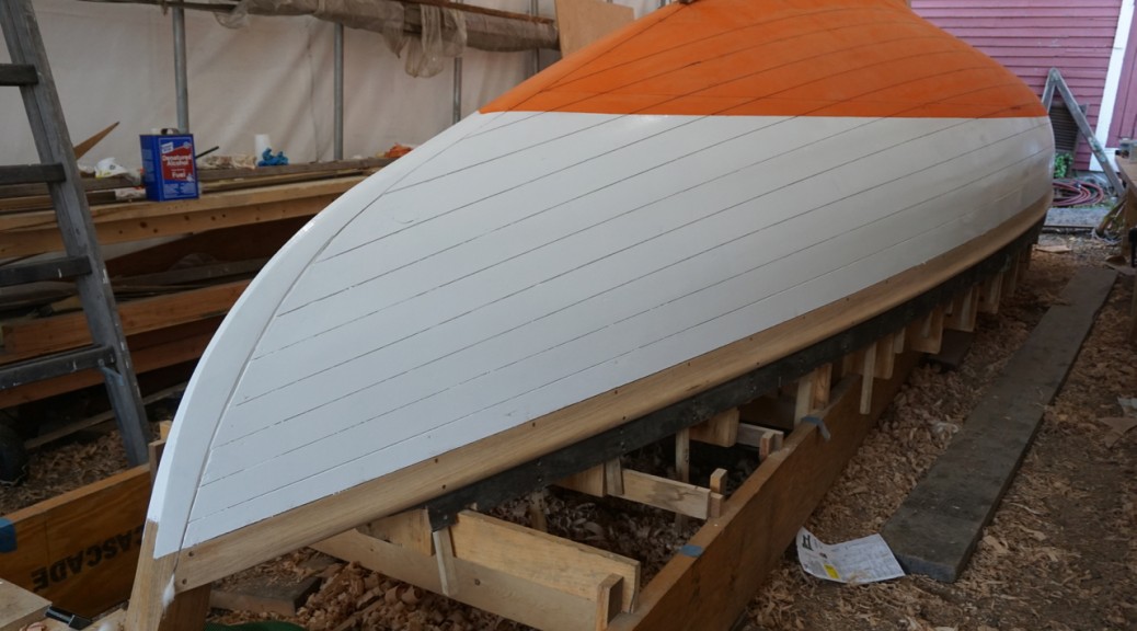
This past fall and winter we have been working away doing a full restoration on an early Herreshoff S-class. The boat has been sitting on the hard in Marblehead for about 20 years after being damaged in a yard fire. Some restoration work had been started under the previous owner, but our hope is to get her back as close to her original shape as possible for racing in the Narragansett fleet. With this goal and an almost 100 year old boat almost all of the hull will need to be replaced. Below are some photos of our progress thus far.

previous restoration work was holding in a lot of deformity in the hull from decades of sitting on poppets and sagging sheer.
as we got the restoration started the remaining interior was removed to be refinished and hopefully replaced.
Some older plaking was still in place, but it is so old that it has become very brittle and weak so it will not be re-used after the restoration.
Aft view of the hull before restoration. Showing some old material and some from a previously started restoration.
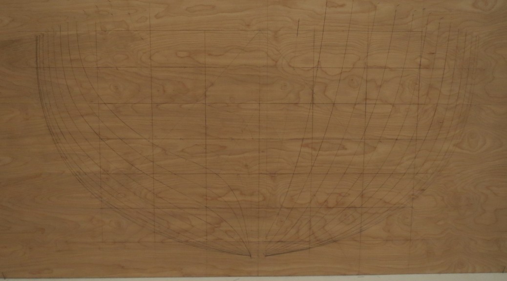
Using measurments taken from the original NGH half model we lofted the boat full size to use as our ultimate shape, trying to take into consideration changes made before this boat might have been built.
a mold was made to the inside of all the even franes to dictate the shape as the restoration comneced.
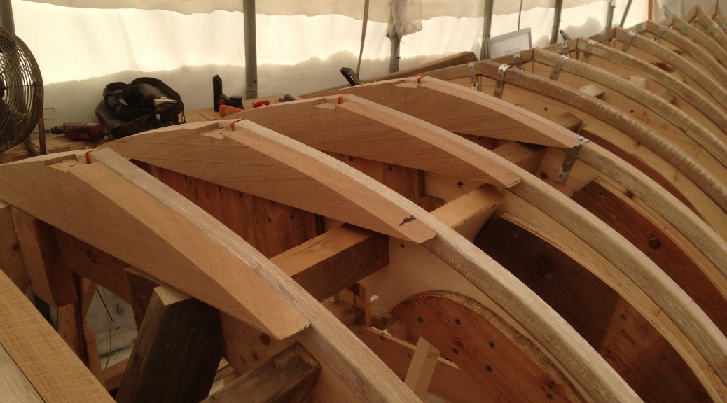
Herreshoff specified tapered frames, lowering the boat's weight where he could.
Herreshoff specified tapered frames, lowering the boat’s weight where he could.
Floor timbers were made from templates lifted straight from the lofting
The molds were inserted into the hull with frames and floor timbers attached
With molds in the existing planking was doubled up to be used as ribbands as the odd frames were bent in.
The transom frame was build up of a few peices carved and steambent to the correct camber.
Transom knee and stem were found in a single oak knee.
With the frames and floors installed the hull was separated from the balast keel and deadwood.
The lead balast and deadwood were wedged open to expose the keel bolts which were cut to separate the hull.
With the ballast removed a ladder frame was built level under the hull to serve as a strong back for the restoration of the hull
With the mast on the bench, the ballast and deadwood away from the hull, and the hull on the strong-back, all major components of the restoration can be worked on simultaneously.

The full length keel was steamed in a bag for 2 hours before being bent on to the building plug.
Once clamped down and cooled the keel was fitted to the upper deadwood and oak backer as well as bolted to the floor timbers.
Gunning dory rig up

Marblehead Gunning Dory

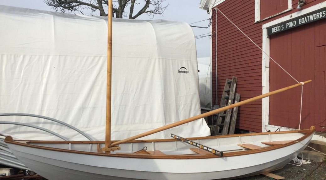
This boat was built new in the fall of 2016 to designs found in John Gardner’s Dory Book. I used the lines of Gerald Smith’s 17′ version he adapted from the original Chamberlin molds that he had acquired. Working with the owner I developed a mix of details from a number of dorys to make sure he had exactly what he wanted. We also added an adapted version of the Beachcomber dory rig John Gardner presents in the 19′ Marblehead Gunning Dory. The hull is planked in cedar, the stem,  sawn and bent frames, and inwale and sheer cap are of oak. Copper rivets and bronze screws. The rig is solid sitka spruce.

Below is a brief description of our dory building process for this boat.

IMG_2620
Bottom board assembly

First, here is the bottom board made up with each station’s frame fastened on along with bow and stern stems and bottom board cleats. I Then flipped this assembly over onto a sturdy building jig which allows me to both plank more comfortably and hold the boat to shape while I bend on the planks. 

Here is the boat right after being flipped off of the planking jig. I leave the frames extra long to make sure that the boat holds it correct width at the stations and each cross brace is made specially so that the bottom board has the right amount of camber in it.

IMG_2787
Flipped

Lucky to get some VERY clear cedar from Florida for this boat. This photo is taken while the seams are riveted tight to keep the hull water tight.

IMG_2789
riveting

Once riveted I moved on to seat risers and thwarts. These enabled me to remove the cross braces and install the inwale to stiffen up the sheer plank.

IMG_2836
Inwale install

Once the inwale was installed I removed the thwarts and seat risers again to install steam bent frames between the sawn frames and the centerboard trunk.

IMG_3028
Centerboard trunk install

The hull is coated in Linseed oil based Varnish and paint allowing good protection while moving with the seasonal dry/swell cycles. Here the centerboat trunk cap is being fit with the bronze rod centerboard lifing bar.


IMG_3199
Centerboard trunk cap

The spars are made of 2 face glued pieces of sitka spruce. By inverting two pieces of the same board you can achieve a much more stable spar as the tensions in the wood can counter-act each other through the seasons.  Here I am cutting down the squared adn tapered stock to 8 even sides, before 16 and then 32 sides before being sanded to a smooth round.

IMG_3043
Rounding the mast
IMG_3223
Mast alignment

Now with the hull coated, the rig finished and varnished final rig details are completed. Mast partner knees, boom jaws, leathers on all chafe points. removable sole boards, stem fittings for the jib, oar lock sockets, etc.

The beachcomber rig has a great look! I can’t wait to see how she rows and sails.

Gunning dory rig up
Rig side view.
IMG_0282

Woodwind Restoration

Woodwind came to the shop with a recent survey mentioning a few concerns including open plank seams, loose fasteners adn some separation of repairs in the rig. While she was still being actively said in the summers the owner brought her in this past winter to get these issues addressed.

IMG_1923_2
Woodwind on arrival was showing her topsides plank seams and her seams below the waterline were dry and open after a winter out of the water.

The garboards were removed to gain access to the bottoms of the frame ends and their fasteners. Once they were off the floor timbers were more decayed than originally thought. The decision was made to replace the worst of them during  the reframing process.

IMG_2074
Once the garboards were removed the floor timbers showed more decay than they initially revealed.

The frames were bent in from the bottom to enable leaving most of the deck structure in place.

IMG_2077


IMG_2082

While the initially we hoped to just replace half the frames it was found that almost none of the frames aft of the forward bulkhead could hold fasteners.

IMG_0002

The  remaining plank fastenings were replaced and then the hull was refaired. All the finishes were then restored for a cosmetic overhaul.

IMG_0283


IMG_3822

Say When II bottom replacement

When Say When II came to me she had been in storage for about ten years awaiting restoration. There were a number of problems in the bottom that needed attention. In the end we decided to replace all the timber below the chines. Previous restoration attempts had introduced a lot of mixed metals and insufficent wood sealants. WIth various rot throughout her bottom and  considering  her being over 70 years old it was decided everything below the chines would be replaced. We decided the bottom would be double planked with the inner layer laid diagonally and the outter longitudinally like the original, however the layers would be bonded together using modern marine adhesive.


Once The interior was removed, molds were built at each frame to help maintain the shape while the different timbers are replaced.

IMG_2487


A small flipping frame was built as we didnt’ have any overhead lifting gear.

IMG_2536IMG_2537IMG_2538

IMG_2539


The keel showing decay from plain steel bolts mixed with a bronze prop strut and prop shaft.

IMG_0034


Decay along the keel on the old frames

IMG_2582


The planks still had the original canvas gasket between the plank layers, but the bedding compound had long since washed out. Various areas had different solutions to the water seeping through. Some areas had cotton driven in, and others had marine adhesives pushed into the seam.

IMG_2543

The replacement frame parts,

IMG_2770


Replacement keel laminated out of Mahogany.

IMG_2785

Here the old keel is being used to double check the frame spacing on the new keel for the new floor timbers

IMG_0470

Dry fit on the boat.

IMG_2804

New Keel and frames installed

IMG_0554

Diagonal planking

IMG_0568IMG_3314 IMG_0590


Dry fitting the outer longitudinal planking


IMG_3327

The two layers were then bedded together with a rubber gasketing layer of 3M 5200. Once cured the planks were faired smooth

IMG_0671 IMG_3345

Prime coat

IMG_3376

Prepared to flip back over

IMG_0690

IMG_3391 IMG_0702 IMG_0703IMG_3395 IMG_3396 IMG_3400 IMG_3401  IMG_3403 IMG_3404 IMG_3406 IMG_3407 IMG_3408 IMG_3409

The flipping jig worked great, and enabled the boat to be turned over single handed. The heavy deck ballanced well against the bottom so there wasn’t much of a tipping point where it wanted to move on it’s own or out of control like most hulls.


Here the inside of the bottom is ready to be cleaned, primed and then to have the engine and interior reinstalled.

IMG_3420

IMG_1925_2

Framing and floor timbers

This is the first boat I have framed outside in tempatures around zero. I was nervous about the frames being able to retain their heat from the steam box long enough for me to be able to bend them around the mold and get them secured. Because of this concern I gave them all a coat of paint prior to steaming, which helps retain more moisture/heat. The paint sealant and the great framing stock worked great together. They look a bit funny with the steamed paint which will need to be scraped before they get their next coat of paint,  but I only broke a couple frames in the transom where there is a significant recurve and twist.

Once framed I set to making and installing floor timbers. I used a sheet of plastic Mylar to trace a  template off the lofting reduced by only the planking thickness this time, and compared it to the molds. Once satisfied with the fit I took bevels on the hull and transferred them all to the oak. .

IMG_1872
The first few frames bent in place
IMG_1896
With temps around zero I built a quick ultra insulated steam box, but still the condesed steam dripping out would develop icicles.
IMG_1902
The shapes gets trickier in the transom where the recurve pulls up towards the transom and gets tighter and tighter. I had a couple failures, but they mostly went on fairly easy.
IMG_1922_2
Aft end framed. Once the centerline is notched for the keel the shape in the center fills out to a wide deadwood like skeg. More on that in future posts.
IMG_1924
A canoe like shape forward is starting to develop.
IMG_1925_2
Floor timbers are beveled, notched for the keel structure and drilled for the keel bolts before instalation. Here you can really see the funny color of the steamed paint next to the fresh oak of the floors.
IMG_1817

Making frame molds & setting up the plug.


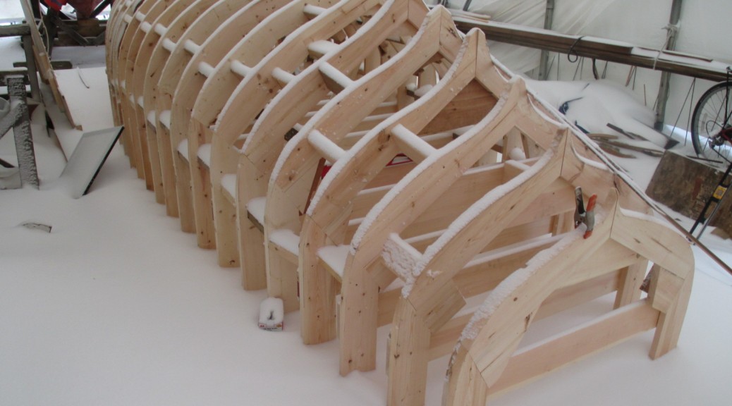
Once the lofting was finished and pulled up from the floor I set to building a bending mold for each frame of the hull. These Molds when fastened to the floor will serve as a building plug. As we have gone to such lengths to build a classic Herreshoff design I thought it most appropriate to build it in the Herreshoff method.  This involves making a mold for each frame station. it can be time consuming, it allows you  to retain as much of those nice lines from the lofting as possible and thus minimizes time spent fairing wood later. Also since the molds are symetrical around the centerline a lot of time can be saved by building each mold doubled up in half.  A slight complication is that these molds will have the frames steam bent over them and then those frames will be planked on top of that. The boat was lofted to the outter face of the planks, so I need to make a reduction from the outter surface to the inside of the frame. Where the boat doesn’t have much shape this is easy, but where the boat has more shape this reduction can get more complicated since it’s being reduced by so much.  Again, a little more time spent on these stages (no actual boat parts have been built at this point) will really pay off throughout the rest of the build.

Once i had fabricated the mold I took a series of bevels from the station view of the lofting which enabled me to do a rough beveling before setting up the frames. Given a very cold winter it was nice to be able to do as much work as possible in teh shop before taking the parts outside. The frames are all set on stations perpendicular to the hull’s centerline, With the nice lofting floor already set up and leveled I am able to set each station up plumb and then structure them all against eachother and against the floor.

IMG_1453
Measuring out the reductions on a a half mold.
IMG_1476
Squaring the doubled over mold to be symetric and fair
IMG_1794
The forward half of the molds, unfolded and reinforced carful of the total width and the centerline
IMG_1795
The aft half of the molds
IMG_1802
The molds, roughly beveled and set up on their stations. The keel area will later be notched to fit the keel assembly.
IMG_1817
After the first major snow of the winter. The stations are all squared and blocked to eachother.
IMG_2241

Lofting An 1882 Steam Launch

Lofting a new build project is a very exciting process. Especially after about a year of development and preparation this was the point where the project finally felt like it was mine. I always enjoy lofting because, for me, this is when I really get a feel for what the boat is going to look like.

Building a boat to a design of this era poses some unique difficulties.  On one hand the MIT Hart Collection has the table of offsets and a drafting of the original boat. Those combined with Zurn Yacht Design’s scaled computer model  gave me a great starting point for the hull shape, but how the boat is going to be built and held together is left mostly untold. The Herreshoff plans offer some details but left out are a lot of construction details about how it’s all held together in a lot of tricky areas. This is often left to the builder.


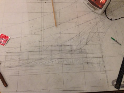
My first step was to draw the shape of the hull full size on a lofting floor. This is done in 3 different views. One is from the front on, one is from the side and one is looking down. Each drawing thus has two dimensions sharing one dimension with each of the others. The boat’s shape is then given as a series of points along a grid set up in all of these drawings. I could go on at great length about the importance of accurate, consistent measuring, or error due to width of pencil lines or simply how much your knees hurt after crawling around on the floor for a few days, but instead I have the below video showing some of the process.


(a short stop motion of the lofting process sorry about the bad lighting, I have since adjusted the camera and have been able to get a better video for the rest of the build)

With the shape of the hull drawn out full size I started to develop how I am going to build it.  Since this is such a historical boat, the goal is to build it as consistent with the original as possible. Here the difficulty arrises.

HMCo was lucky and ultimately as successful as it was because they had a genius designer in-house.  The design was conceived in one building and then built and launched across the street. They also had the benefit of hundreds of years of cumulative boatbuilding knowledge on the floor.  It is said that Nat Herreshoff would make daily visits to the yard and he would often make adjustments to a design long after construction had started and all drafting had been completed. There is little record of any of these later tweaks and changes made on the drafting. Pulling lines off of a well-preserved boat might have provided some insight. However,  since neither  the original boat nor any like it exists today, a lot of problem solving still exists. As tedious as this process may be, I really enjoy the challenge.

The first step in filling in the gaps was to go back to the MIT Hart collection and get as much information as I could about the original boat.  Herreshoff built many steam launches  in the 1800’s, and early 1900’s and I was able to get copies of plans for several similar launches which included different views or details which showed a few more details about how different areas may have been built.

a printed scan of the original plans at MIT's Hart museum
a printed scan of the original plans at MIT’s Hart museum


Next I took these plans to the lofting floor and started drawing in various parts of the boat. Some are straight forward. For example, the keel has a precise width and thickness that starts and ends at specific points as shown on the plans. Other parts however needed a lot more investigation.

An example of a very tricky area to figure out was where the propeller shaft goes through the counter timber assembly at the back of the boat. There is a lot going on in this area, there is a large hole drilled through hull well below the water line with a lot of force applied by the rudder, and the propeller.  With all this it is prone to rot and it needs to be built especially strong. The plans show a very simple representation of the area. Once drawn on the lofting floor it seems that there wasn’t nearly enough space to fit all of the necessary parts into such a small space and have it hold together.

This is a picture of the drafting of the stern. showing all the info I have to work from on the original


Problem solving a trouble prone area like this in an old boat is often a balance between recreating it’s original design and drawing on modern knowledge. With this in mind I approached a few aspects of the area to try and get it right.

The first thing I wanted to change was simply the size of the prop shaft. The original was 1880’s rolled brass and was for a much larger engine, so I could bring it’s diameter down by about a half using silicon bronze appropriately sized for this boat and it’s engine. This was an improvement, but still didn’t leave enough strength for me to feel comfortable.

The next problem was two-fold; I wanted the area to resist rot and be easy to reconstruct if rot were to sneak in over time. As shown in the above pictures there are no details about how this area is held together structurally. So to develop a plan I looked through as many boatbuilding texts as I could get my hands on, I poured through as many images and boat plans old and new as I could and had a conversation with  Walter Ansel who is restoring a similar boat at the Wooden Boat School, and Warren Barker who has been a part of many restorations of  Herreshoff boats. From all of this I decided to make a 2 part shaft log as opposed to the solid one in the plans. This would enable me to bolt together the area in such a way that the shaft log and tube could be more easily replaced without deconstructing the whole boat. I also widened the structural pieces around the shaft. This allows me to move the move the plank ends further forward and up into the boat. Without the planks stealing 3/4″ of width through this area I could make space for the prop shaft, bolts around it, and enough timber to be strong enough to handle the forces generated by the prop and rudder.

This is a picture of the drafting of the stern. showing all the info I have to work from on the original


my scrap sheet of where the planking, bolts and prop shaft can all fit together.
another station further aft showing how narrow the hull gets and how tight it becomes to fit planking, prop shaft and enough structure to hold it all together. see how I have moved the plank ends up out of the wat where there is enough width to get bolts around the stern tube.
another station further aft showing how narrow the hull gets and how tight it becomes to fit planking, prop shaft and enough structure to hold it all together. see how I have moved the plank ends up out of the way where there is enough width to get bolts around the stern tube.
similar counter timber area with rabbet pushed away from the trailing edge leving enough timber around the shaft tube to provide space for timber structure and bolts.


after a lot of erasing and redrawing this is what the lofting floor looked like around the counter timber.

Ultimately I doubt that this construction is exactly what  HMCo used, and in that it is probably a deviation from a strict “replica”. However, without an original to build from, this solution best satisfies my  concerns of serviceability and longevity while staying as true to the original as I can.

Some might find that I gave too much detail on that one problem I had to solve, but it’s a nice example of the benefit of lofting and took up a lot of my time in and out of the shop. Had I gone straight into building the backbone I would have had a lot of trouble when I went to plank the hull or drill for the stern tube and realized the boat didn’t have enough structure there to hold together. I have learned that plotting these details out in advance ultimately saves a lot of time and yields a better boat.


History of the design.

I am very excited to be building a steam powered wooden launch from a scaled-down Nat Herreshoff design. Throughout the process, I will be posting here so that those who are interested can keep up to date. To start with I’d like to give some history to the design we choose, and how we went about having the boat scaled down to produce the hull I will be building.

No-94
http://pds.lib.harvard.edu/pds/view/10835441?n=39&imagesize=1200&jp2Res=.25&printThumbnails=no
http://www.machine-history.com/Herreshoff%20Manufacturing%20Company%201800s

The primary design was boat No 94 from the Herreshoff Manufacturing Company (HMCo.) It was built only once for the United States Fish Commission to be used as a steam cutter for the USS Albatross. The Albatross was built in 1882 and out of the 8 boats that she carried No 94 was one of two steam powered boats built by HMCo. The other one had a very interesting center propeller attached to a universal joint that could be retracted when not in use or when it entered shallow water. Both boats had auxiliary schooner rigs and reportedly moved along nicely under sail alone.


Interesting account of Albatross, her construction and the research done on-board.


The 26′ No. 94 was built to steam for 3 days and hold 12 passengers when going on marine research voyages from the larger (234’) Albatross. I haven’t yet found out what happened to the original boat but I assume it was lost or broken up, as later photos of the Albatross don’t show this boat. As with all Herreshoff designed boat, the lines are pulled from a half model and then scaled to the desired size.

http://newenglandboating.com/videos/video-how-herreshoff-designed-his-boats.html


After Nat Herreshoff carved a half model he would create a table of offsets and then it could be scaled to the appropriate size. The table of offsets for No 94 were  also used for many different boats ranging of 20′ to 50′.  To accomplish the various scales, Herreshoff used a variety of methods. One was to proportionately scale in all dimensions. Another way was to stretch the center section of the boat. The final method was to keep the width and height of each frame the same and adjust the spacing between them.


We had a challenge with the scaling on this project. The owner’s vision is to be able to steam around Marblehead Harbor as opposed to 3 straight days in the Arctic and with 4 passengers rather than 12. Most importantly her berth requires a length of no more than 23’. Thus while the owner loved the look of No. 94 he needed to have it made smaller than the original. As we approached the process of scaling down the original design the goal was to keep as much free-board and beam as possible while bringing her down to about 22’ 6”. This would allow for easier handling by the owner while still being seaworthy enough to handle occasional rough water. With these guidelines and the original offsets from HMCo, Doug Zurn of Zurn Yacht Design was able to generate a computer model and scaled down the boat using modern CAD programs. This technology allowed us to achieve the desired size while staying as faithful as possible to the original Herreshoff hull shape.

14143 - PRO 1 14143 010-004


While I move forward with building the hull. I will be working with the owner to find an appropriate engine and boiler combination. With this digital model will be able to see the effects that different combinations would have on stability and displacement.