IMG_0282

Woodwind Restoration

Woodwind came to the shop with a recent survey mentioning a few concerns including open plank seams, loose fasteners adn some separation of repairs in the rig. While she was still being actively said in the summers the owner brought her in this past winter to get these issues addressed.

IMG_1923_2
Woodwind on arrival was showing her topsides plank seams and her seams below the waterline were dry and open after a winter out of the water.

The garboards were removed to gain access to the bottoms of the frame ends and their fasteners. Once they were off the floor timbers were more decayed than originally thought. The decision was made to replace the worst of them during  the reframing process.

IMG_2074
Once the garboards were removed the floor timbers showed more decay than they initially revealed.

The frames were bent in from the bottom to enable leaving most of the deck structure in place.

IMG_2077


IMG_2082

While the initially we hoped to just replace half the frames it was found that almost none of the frames aft of the forward bulkhead could hold fasteners.

IMG_0002

The  remaining plank fastenings were replaced and then the hull was refaired. All the finishes were then restored for a cosmetic overhaul.

IMG_0283


IMG_3822

Say When II bottom replacement

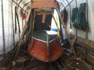
When Say When II came to me she had been in storage for about ten years awaiting restoration. There were a number of problems in the bottom that needed attention. In the end we decided to replace all the timber below the chines. Previous restoration attempts had introduced a lot of mixed metals and insufficent wood sealants. WIth various rot throughout her bottom and  considering  her being over 70 years old it was decided everything below the chines would be replaced. We decided the bottom would be double planked with the inner layer laid diagonally and the outter longitudinally like the original, however the layers would be bonded together using modern marine adhesive.


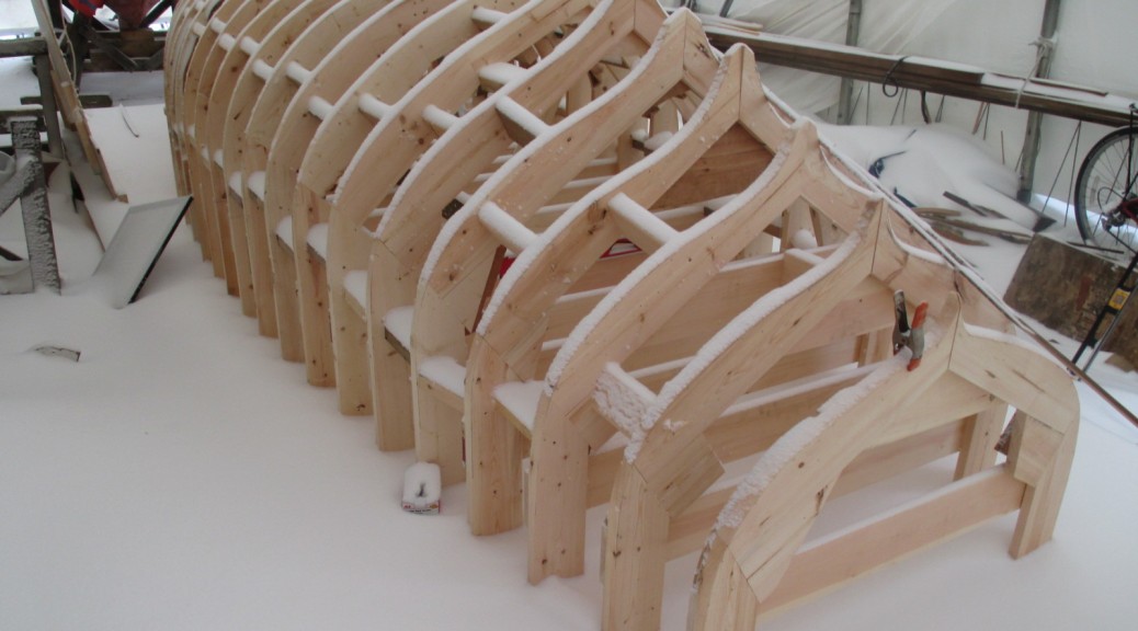
Once The interior was removed, molds were built at each frame to help maintain the shape while the different timbers are replaced.

IMG_2487


A small flipping frame was built as we didnt’ have any overhead lifting gear.

IMG_2536IMG_2537IMG_2538

IMG_2539


The keel showing decay from plain steel bolts mixed with a bronze prop strut and prop shaft.

IMG_0034


Decay along the keel on the old frames

IMG_2582


The planks still had the original canvas gasket between the plank layers, but the bedding compound had long since washed out. Various areas had different solutions to the water seeping through. Some areas had cotton driven in, and others had marine adhesives pushed into the seam.

IMG_2543

The replacement frame parts,

IMG_2770


Replacement keel laminated out of Mahogany.

IMG_2785

Here the old keel is being used to double check the frame spacing on the new keel for the new floor timbers

IMG_0470

Dry fit on the boat.

IMG_2804

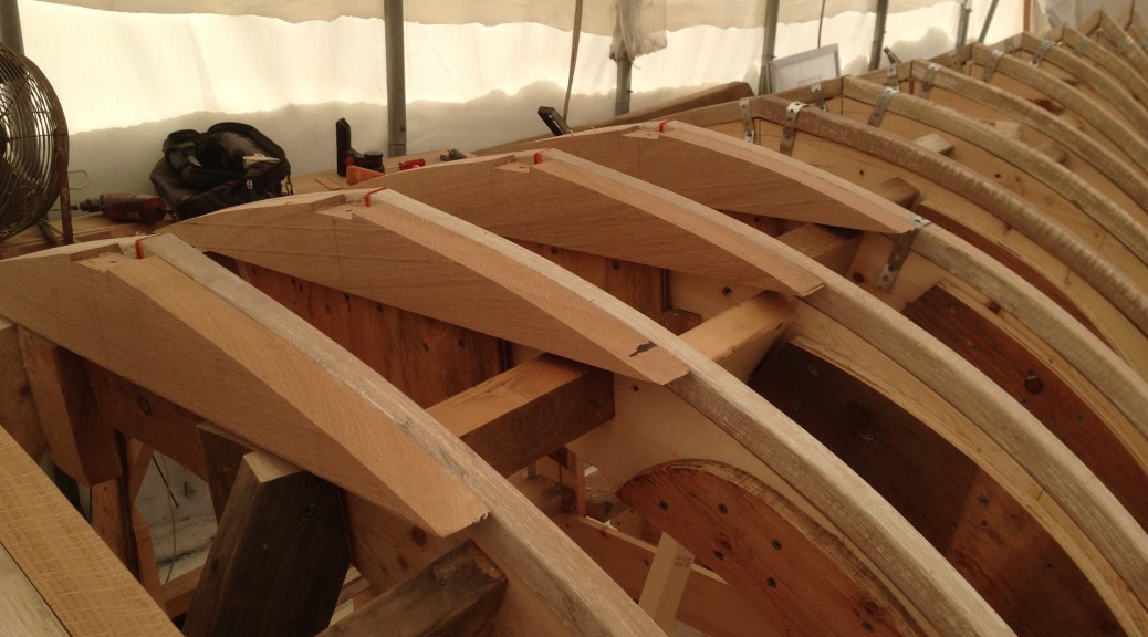
New Keel and frames installed

IMG_0554

Diagonal planking

IMG_0568IMG_3314 IMG_0590


Dry fitting the outer longitudinal planking


IMG_3327

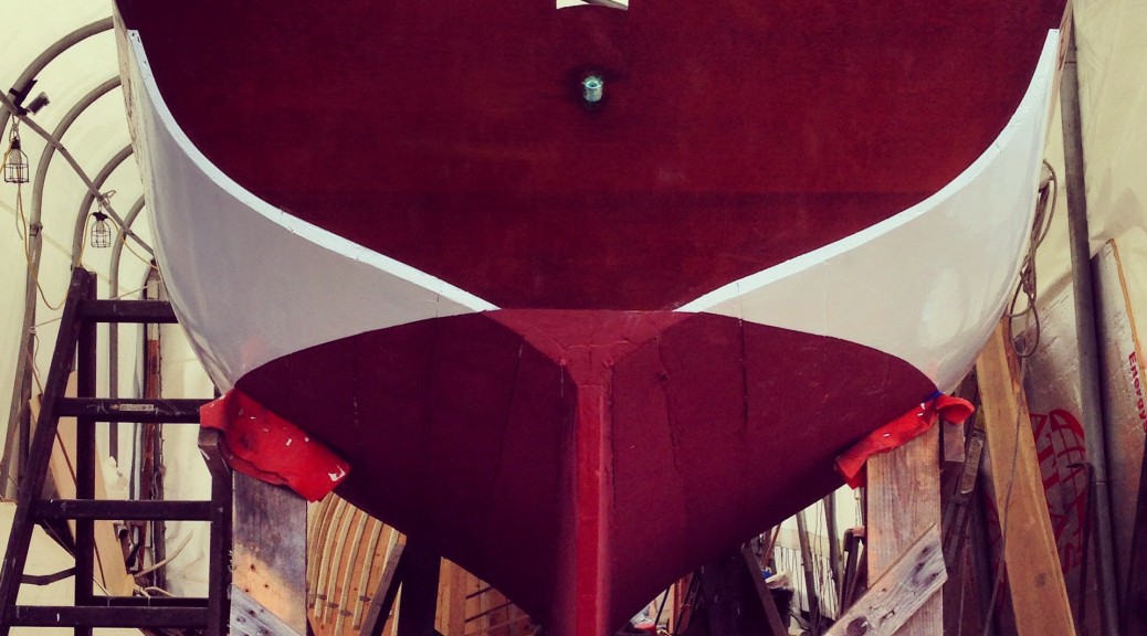
The two layers were then bedded together with a rubber gasketing layer of 3M 5200. Once cured the planks were faired smooth

IMG_0671 IMG_3345

Prime coat

IMG_3376

Prepared to flip back over

IMG_0690

IMG_3391 IMG_0702 IMG_0703IMG_3395 IMG_3396 IMG_3400 IMG_3401  IMG_3403 IMG_3404 IMG_3406 IMG_3407 IMG_3408 IMG_3409

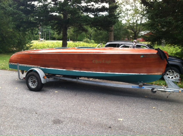
The flipping jig worked great, and enabled the boat to be turned over single handed. The heavy deck ballanced well against the bottom so there wasn’t much of a tipping point where it wanted to move on it’s own or out of control like most hulls.


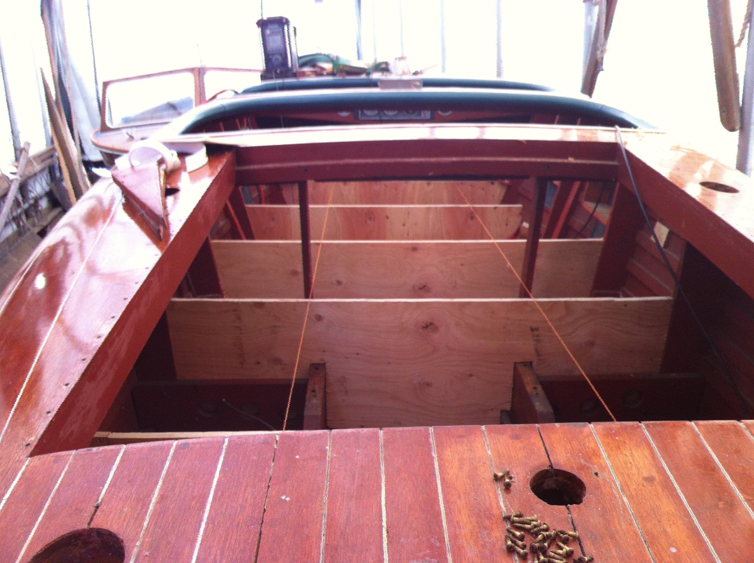
Here the inside of the bottom is ready to be cleaned, primed and then to have the engine and interior reinstalled.

IMG_3420

IMG_1925_2

Framing and floor timbers

This is the first boat I have framed outside in tempatures around zero. I was nervous about the frames being able to retain their heat from the steam box long enough for me to be able to bend them around the mold and get them secured. Because of this concern I gave them all a coat of paint prior to steaming, which helps retain more moisture/heat. The paint sealant and the great framing stock worked great together. They look a bit funny with the steamed paint which will need to be scraped before they get their next coat of paint,  but I only broke a couple frames in the transom where there is a significant recurve and twist.

Once framed I set to making and installing floor timbers. I used a sheet of plastic Mylar to trace a  template off the lofting reduced by only the planking thickness this time, and compared it to the molds. Once satisfied with the fit I took bevels on the hull and transferred them all to the oak. .

IMG_1872
The first few frames bent in place
IMG_1896
With temps around zero I built a quick ultra insulated steam box, but still the condesed steam dripping out would develop icicles.
IMG_1902
The shapes gets trickier in the transom where the recurve pulls up towards the transom and gets tighter and tighter. I had a couple failures, but they mostly went on fairly easy.
IMG_1922_2
Aft end framed. Once the centerline is notched for the keel the shape in the center fills out to a wide deadwood like skeg. More on that in future posts.
IMG_1924
A canoe like shape forward is starting to develop.
IMG_1925_2
Floor timbers are beveled, notched for the keel structure and drilled for the keel bolts before instalation. Here you can really see the funny color of the steamed paint next to the fresh oak of the floors.
IMG_1817

Making frame molds & setting up the plug.


Once the lofting was finished and pulled up from the floor I set to building a bending mold for each frame of the hull. These Molds when fastened to the floor will serve as a building plug. As we have gone to such lengths to build a classic Herreshoff design I thought it most appropriate to build it in the Herreshoff method.  This involves making a mold for each frame station. it can be time consuming, it allows you  to retain as much of those nice lines from the lofting as possible and thus minimizes time spent fairing wood later. Also since the molds are symetrical around the centerline a lot of time can be saved by building each mold doubled up in half.  A slight complication is that these molds will have the frames steam bent over them and then those frames will be planked on top of that. The boat was lofted to the outter face of the planks, so I need to make a reduction from the outter surface to the inside of the frame. Where the boat doesn’t have much shape this is easy, but where the boat has more shape this reduction can get more complicated since it’s being reduced by so much.  Again, a little more time spent on these stages (no actual boat parts have been built at this point) will really pay off throughout the rest of the build.

Once i had fabricated the mold I took a series of bevels from the station view of the lofting which enabled me to do a rough beveling before setting up the frames. Given a very cold winter it was nice to be able to do as much work as possible in teh shop before taking the parts outside. The frames are all set on stations perpendicular to the hull’s centerline, With the nice lofting floor already set up and leveled I am able to set each station up plumb and then structure them all against eachother and against the floor.

IMG_1453
Measuring out the reductions on a a half mold.
IMG_1476
Squaring the doubled over mold to be symetric and fair
IMG_1794
The forward half of the molds, unfolded and reinforced carful of the total width and the centerline
IMG_1795
The aft half of the molds
IMG_1802
The molds, roughly beveled and set up on their stations. The keel area will later be notched to fit the keel assembly.
IMG_1817
After the first major snow of the winter. The stations are all squared and blocked to eachother.