
Lofting a new build project is a very exciting process. Especially after about a year of development and preparation this was the point where the project finally felt like it was mine. I always enjoy lofting because, for me, this is when I really get a feel for what the boat is going to look like.
Building a boat to a design of this era poses some unique difficulties. On one hand the MIT Hart Collection has the table of offsets and a drafting of the original boat. Those combined with Zurn Yacht Design’s scaled computer model gave me a great starting point for the hull shape, but how the boat is going to be built and held together is left mostly untold. The Herreshoff plans offer some details but left out are a lot of construction details about how it’s all held together in a lot of tricky areas. This is often left to the builder.
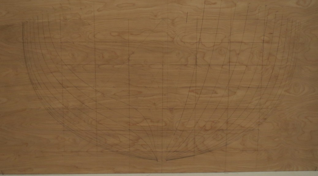
My first step was to draw the shape of the hull full size on a lofting floor. This is done in 3 different views. One is from the front on, one is from the side and one is looking down. Each drawing thus has two dimensions sharing one dimension with each of the others. The boat’s shape is then given as a series of points along a grid set up in all of these drawings. I could go on at great length about the importance of accurate, consistent measuring, or error due to width of pencil lines or simply how much your knees hurt after crawling around on the floor for a few days, but instead I have the below video showing some of the process.
(a short stop motion of the lofting process sorry about the bad lighting, I have since adjusted the camera and have been able to get a better video for the rest of the build)
With the shape of the hull drawn out full size I started to develop how I am going to build it. Since this is such a historical boat, the goal is to build it as consistent with the original as possible. Here the difficulty arrises.
HMCo was lucky and ultimately as successful as it was because they had a genius designer in-house. The design was conceived in one building and then built and launched across the street. They also had the benefit of hundreds of years of cumulative boatbuilding knowledge on the floor. It is said that Nat Herreshoff would make daily visits to the yard and he would often make adjustments to a design long after construction had started and all drafting had been completed. There is little record of any of these later tweaks and changes made on the drafting. Pulling lines off of a well-preserved boat might have provided some insight. However, since neither the original boat nor any like it exists today, a lot of problem solving still exists. As tedious as this process may be, I really enjoy the challenge.
The first step in filling in the gaps was to go back to the MIT Hart collection and get as much information as I could about the original boat. Herreshoff built many steam launches in the 1800’s, and early 1900’s and I was able to get copies of plans for several similar launches which included different views or details which showed a few more details about how different areas may have been built.

Next I took these plans to the lofting floor and started drawing in various parts of the boat. Some are straight forward. For example, the keel has a precise width and thickness that starts and ends at specific points as shown on the plans. Other parts however needed a lot more investigation.
An example of a very tricky area to figure out was where the propeller shaft goes through the counter timber assembly at the back of the boat. There is a lot going on in this area, there is a large hole drilled through hull well below the water line with a lot of force applied by the rudder, and the propeller. With all this it is prone to rot and it needs to be built especially strong. The plans show a very simple representation of the area. Once drawn on the lofting floor it seems that there wasn’t nearly enough space to fit all of the necessary parts into such a small space and have it hold together.

Problem solving a trouble prone area like this in an old boat is often a balance between recreating it’s original design and drawing on modern knowledge. With this in mind I approached a few aspects of the area to try and get it right.
The first thing I wanted to change was simply the size of the prop shaft. The original was 1880’s rolled brass and was for a much larger engine, so I could bring it’s diameter down by about a half using silicon bronze appropriately sized for this boat and it’s engine. This was an improvement, but still didn’t leave enough strength for me to feel comfortable.
The next problem was two-fold; I wanted the area to resist rot and be easy to reconstruct if rot were to sneak in over time. As shown in the above pictures there are no details about how this area is held together structurally. So to develop a plan I looked through as many boatbuilding texts as I could get my hands on, I poured through as many images and boat plans old and new as I could and had a conversation with Walter Ansel who is restoring a similar boat at the Wooden Boat School, and Warren Barker who has been a part of many restorations of Herreshoff boats. From all of this I decided to make a 2 part shaft log as opposed to the solid one in the plans. This would enable me to bolt together the area in such a way that the shaft log and tube could be more easily replaced without deconstructing the whole boat. I also widened the structural pieces around the shaft. This allows me to move the move the plank ends further forward and up into the boat. Without the planks stealing 3/4″ of width through this area I could make space for the prop shaft, bolts around it, and enough timber to be strong enough to handle the forces generated by the prop and rudder.


Ultimately I doubt that this construction is exactly what HMCo used, and in that it is probably a deviation from a strict “replica”. However, without an original to build from, this solution best satisfies my concerns of serviceability and longevity while staying as true to the original as I can.
Some might find that I gave too much detail on that one problem I had to solve, but it’s a nice example of the benefit of lofting and took up a lot of my time in and out of the shop. Had I gone straight into building the backbone I would have had a lot of trouble when I went to plank the hull or drill for the stern tube and realized the boat didn’t have enough structure there to hold together. I have learned that plotting these details out in advance ultimately saves a lot of time and yields a better boat.