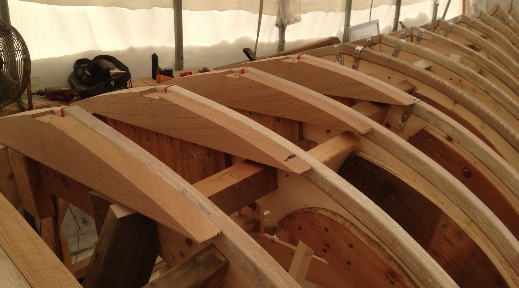
This is the first boat I have framed outside in tempatures around zero. I was nervous about the frames being able to retain their heat from the steam box long enough for me to be able to bend them around the mold and get them secured. Because of this concern I gave them all a coat of paint prior to steaming, which helps retain more moisture/heat. The paint sealant and the great framing stock worked great together. They look a bit funny with the steamed paint which will need to be scraped before they get their next coat of paint, but I only broke a couple frames in the transom where there is a significant recurve and twist.
Once framed I set to making and installing floor timbers. I used a sheet of plastic Mylar to trace a template off the lofting reduced by only the planking thickness this time, and compared it to the molds. Once satisfied with the fit I took bevels on the hull and transferred them all to the oak. .
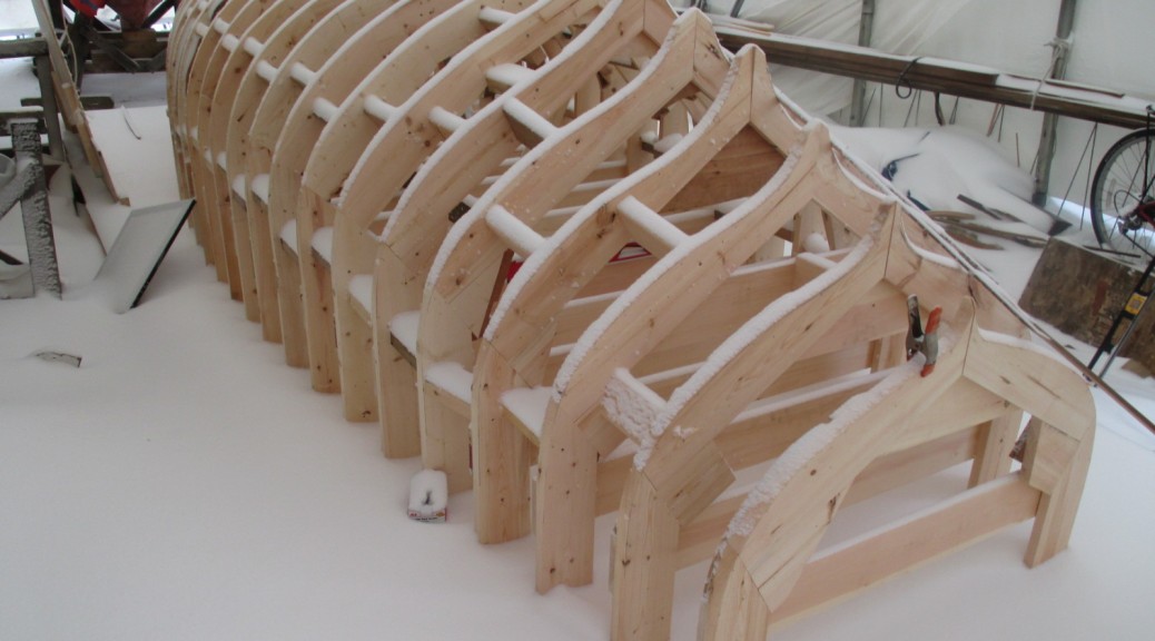
The first few frames bent in placeWith temps around zero I built a quick ultra insulated steam box, but still the condesed steam dripping out would develop icicles.The shapes gets trickier in the transom where the recurve pulls up towards the transom and gets tighter and tighter. I had a couple failures, but they mostly went on fairly easy.Aft end framed. Once the centerline is notched for the keel the shape in the center fills out to a wide deadwood like skeg. More on that in future posts.A canoe like shape forward is starting to develop.Floor timbers are beveled, notched for the keel structure and drilled for the keel bolts before instalation. Here you can really see the funny color of the steamed paint next to the fresh oak of the floors.
Once the lofting was finished and pulled up from the floor I set to building a bending mold for each frame of the hull. These Molds when fastened to the floor will serve as a building plug. As we have gone to such lengths to build a classic Herreshoff design I thought it most appropriate to build it in the Herreshoff method. This involves making a mold for each frame station. it can be time consuming, it allows you to retain as much of those nice lines from the lofting as possible and thus minimizes time spent fairing wood later. Also since the molds are symetrical around the centerline a lot of time can be saved by building each mold doubled up in half. A slight complication is that these molds will have the frames steam bent over them and then those frames will be planked on top of that. The boat was lofted to the outter face of the planks, so I need to make a reduction from the outter surface to the inside of the frame. Where the boat doesn’t have much shape this is easy, but where the boat has more shape this reduction can get more complicated since it’s being reduced by so much. Again, a little more time spent on these stages (no actual boat parts have been built at this point) will really pay off throughout the rest of the build.
Once i had fabricated the mold I took a series of bevels from the station view of the lofting which enabled me to do a rough beveling before setting up the frames. Given a very cold winter it was nice to be able to do as much work as possible in teh shop before taking the parts outside. The frames are all set on stations perpendicular to the hull’s centerline, With the nice lofting floor already set up and leveled I am able to set each station up plumb and then structure them all against eachother and against the floor.
Measuring out the reductions on a a half mold.Squaring the doubled over mold to be symetric and fairThe forward half of the molds, unfolded and reinforced carful of the total width and the centerlineThe aft half of the moldsThe molds, roughly beveled and set up on their stations. The keel area will later be notched to fit the keel assembly.After the first major snow of the winter. The stations are all squared and blocked to eachother.
Lofting a new build project is a very exciting process. Especially after about a year of development and preparation this was the point where the project finally felt like it was mine. I always enjoy lofting because, for me, this is when I really get a feel for what the boat is going to look like.
Building a boat to a design of this era poses some unique difficulties. On one hand the MIT Hart Collection has the table of offsets and a drafting of the original boat. Those combined with Zurn Yacht Design’s scaled computer model gave me a great starting point for the hull shape, but how the boat is going to be built and held together is left mostly untold. The Herreshoff plans offer some details but left out are a lot of construction details about how it’s all held together in a lot of tricky areas. This is often left to the builder.
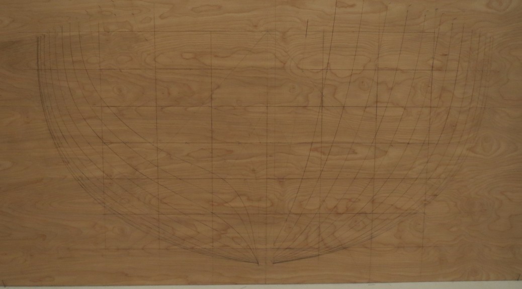
My first step was to draw the shape of the hull full size on a lofting floor. This is done in 3 different views. One is from the front on, one is from the side and one is looking down. Each drawing thus has two dimensions sharing one dimension with each of the others. The boat’s shape is then given as a series of points along a grid set up in all of these drawings. I could go on at great length about the importance of accurate, consistent measuring, or error due to width of pencil lines or simply how much your knees hurt after crawling around on the floor for a few days, but instead I have the below video showing some of the process.
(a short stop motion of the lofting process sorry about the bad lighting, I have since adjusted the camera and have been able to get a better video for the rest of the build)
With the shape of the hull drawn out full size I started to develop how I am going to build it. Since this is such a historical boat, the goal is to build it as consistent with the original as possible. Here the difficulty arrises.
HMCo was lucky and ultimately as successful as it was because they had a genius designer in-house. The design was conceived in one building and then built and launched across the street. They also had the benefit of hundreds of years of cumulative boatbuilding knowledge on the floor. It is said that Nat Herreshoff would make daily visits to the yard and he would often make adjustments to a design long after construction had started and all drafting had been completed. There is little record of any of these later tweaks and changes made on the drafting. Pulling lines off of a well-preserved boat might have provided some insight. However, since neither the original boat nor any like it exists today, a lot of problem solving still exists. As tedious as this process may be, I really enjoy the challenge.
The first step in filling in the gaps was to go back to the MIT Hart collection and get as much information as I could about the original boat. Herreshoff built many steam launches in the 1800’s, and early 1900’s and I was able to get copies of plans for several similar launches which included different views or details which showed a few more details about how different areas may have been built.
a printed scan of the original plans at MIT’s Hart museum
Next I took these plans to the lofting floor and started drawing in various parts of the boat. Some are straight forward. For example, the keel has a precise width and thickness that starts and ends at specific points as shown on the plans. Other parts however needed a lot more investigation.
An example of a very tricky area to figure out was where the propeller shaft goes through the counter timber assembly at the back of the boat. There is a lot going on in this area, there is a large hole drilled through hull well below the water line with a lot of force applied by the rudder, and the propeller. With all this it is prone to rot and it needs to be built especially strong. The plans show a very simple representation of the area. Once drawn on the lofting floor it seems that there wasn’t nearly enough space to fit all of the necessary parts into such a small space and have it hold together.
This is a picture of the drafting of the stern. showing all the info I have to work from on the original
Problem solving a trouble prone area like this in an old boat is often a balance between recreating it’s original design and drawing on modern knowledge. With this in mind I approached a few aspects of the area to try and get it right.
The first thing I wanted to change was simply the size of the prop shaft. The original was 1880’s rolled brass and was for a much larger engine, so I could bring it’s diameter down by about a half using silicon bronze appropriately sized for this boat and it’s engine. This was an improvement, but still didn’t leave enough strength for me to feel comfortable.
The next problem was two-fold; I wanted the area to resist rot and be easy to reconstruct if rot were to sneak in over time. As shown in the above pictures there are no details about how this area is held together structurally. So to develop a plan I looked through as many boatbuilding texts as I could get my hands on, I poured through as many images and boat plans old and new as I could and had a conversation with Walter Ansel who is restoring a similar boat at the Wooden Boat School, and Warren Barker who has been a part of many restorations of Herreshoff boats. From all of this I decided to make a 2 part shaft log as opposed to the solid one in the plans. This would enable me to bolt together the area in such a way that the shaft log and tube could be more easily replaced without deconstructing the whole boat. I also widened the structural pieces around the shaft. This allows me to move the move the plank ends further forward and up into the boat. Without the planks stealing 3/4″ of width through this area I could make space for the prop shaft, bolts around it, and enough timber to be strong enough to handle the forces generated by the prop and rudder.
This is a picture of the drafting of the stern. showing all the info I have to work from on the original
my scrap sheet of where the planking, bolts and prop shaft can all fit together.another station further aft showing how narrow the hull gets and how tight it becomes to fit planking, prop shaft and enough structure to hold it all together. see how I have moved the plank ends up out of the way where there is enough width to get bolts around the stern tube.similar counter timber area with rabbet pushed away from the trailing edge leving enough timber around the shaft tube to provide space for timber structure and bolts.
after a lot of erasing and redrawing this is what the lofting floor looked like around the counter timber.
Ultimately I doubt that this construction is exactly what HMCo used, and in that it is probably a deviation from a strict “replica”. However, without an original to build from, this solution best satisfies my concerns of serviceability and longevity while staying as true to the original as I can.
Some might find that I gave too much detail on that one problem I had to solve, but it’s a nice example of the benefit of lofting and took up a lot of my time in and out of the shop. Had I gone straight into building the backbone I would have had a lot of trouble when I went to plank the hull or drill for the stern tube and realized the boat didn’t have enough structure there to hold together. I have learned that plotting these details out in advance ultimately saves a lot of time and yields a better boat.
I am very excited to be building a steam powered wooden launch from a scaled-down Nat Herreshoff design. Throughout the process, I will be posting here so that those who are interested can keep up to date. To start with I’d like to give some history to the design we choose, and how we went about having the boat scaled down to produce the hull I will be building.
The primary design was boat No 94 from the Herreshoff Manufacturing Company (HMCo.) It was built only once for the United States Fish Commission to be used as a steam cutter for the USS Albatross. The Albatross was built in 1882 and out of the 8 boats that she carried No 94 was one of two steam powered boats built by HMCo. The other one had a very interesting center propeller attached to a universal joint that could be retracted when not in use or when it entered shallow water. Both boats had auxiliary schooner rigs and reportedly moved along nicely under sail alone.
The 26′ No. 94 was built to steam for 3 days and hold 12 passengers when going on marine research voyages from the larger (234’) Albatross. I haven’t yet found out what happened to the original boat but I assume it was lost or broken up, as later photos of the Albatross don’t show this boat. As with all Herreshoff designed boat, the lines are pulled from a half model and then scaled to the desired size.
After Nat Herreshoff carved a half model he would create a table of offsets and then it could be scaled to the appropriate size. The table of offsets for No 94 were also used for many different boats ranging of 20′ to 50′. To accomplish the various scales, Herreshoff used a variety of methods. One was to proportionately scale in all dimensions. Another way was to stretch the center section of the boat. The final method was to keep the width and height of each frame the same and adjust the spacing between them.
We had a challenge with the scaling on this project. The owner’s vision is to be able to steam around Marblehead Harbor as opposed to 3 straight days in the Arctic and with 4 passengers rather than 12. Most importantly her berth requires a length of no more than 23’. Thus while the owner loved the look of No. 94 he needed to have it made smaller than the original. As we approached the process of scaling down the original design the goal was to keep as much free-board and beam as possible while bringing her down to about 22’ 6”. This would allow for easier handling by the owner while still being seaworthy enough to handle occasional rough water. With these guidelines and the original offsets from HMCo, Doug Zurn of Zurn Yacht Design was able to generate a computer model and scaled down the boat using modern CAD programs. This technology allowed us to achieve the desired size while staying as faithful as possible to the original Herreshoff hull shape.
While I move forward with building the hull. I will be working with the owner to find an appropriate engine and boiler combination. With this digital model will be able to see the effects that different combinations would have on stability and displacement.